Welcome to SPOTTURNS page, Greetings from my side with following link GATE HAND WRITTEN NOTES.

Sunday 29 March 2015

computers physical size optimization

Data storage 
Data storage has progressed in leaps and bounds over the last 50 years and will continue to do so for the foreseeable future. Trends have consistently shown exponential growth in this area, making it surprisingly easy to predict future advances. Before we look at these future advances, however, it is perhaps worth looking back at the history of data storage.
In 1956, IBM launched the RAMAC 305 - the first computer with a hard disk drive (HDD). This weighed over a ton and consisted of fifty 24" discs, stacked together in a wardrobe-sized machine. Two independent access arms moved up and down to select a disk, and in and out to select a recording track, all under servo control. The total storage capacity of the RAMAC 305 was 5 million 7-bit characters, or about 4.4 MB.

IBM RAMAC 305 1956 worlds first computer hard disk drive hdd storage 4m 5mb
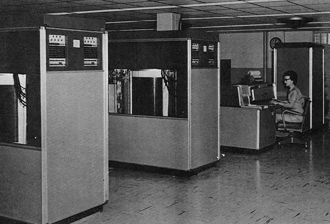
Above: The IBM RAMAC 305

1962 saw the release of the IBM 1311 - the first storage unit with removable disks. Each "disk pack" held around two million characters of information. Users were able to easily switch files for different applications.
Transistor technology - which replaced vacuum tubes - began to substantially reduce the size and cost of computer hardware.
The IBM 3330 was introduced in 1970, with removable disk packs that could hold 100 MB. The 1973 model featured disk packs that held 200 MB (pictured here). Access time was 30 ms and data could be transferred at 800 kB/s.
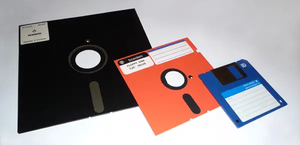
Floppy disks arrived in 1971, revolutionising data storage. Although smaller in capacity, they were extremely lightweight and portable. The earliest versions measured 8 inches in diameter. These were followed by 5¼-inch disks in the late 1970s and 3½-inch disks in the mid-1980s.

floppy disks


The IBM 3380 was introduced in 1980. This mainframe held eight individual drives, each with a capacity of 2.5 GB (pictured here). The drives featured high-performance "cache" memory and transfer speeds of 3 MB/s. Each cabinet was about the size of a refrigerator and weighed 550 lb (250 kg). The price ranged from $648,000 to $1,136,600.
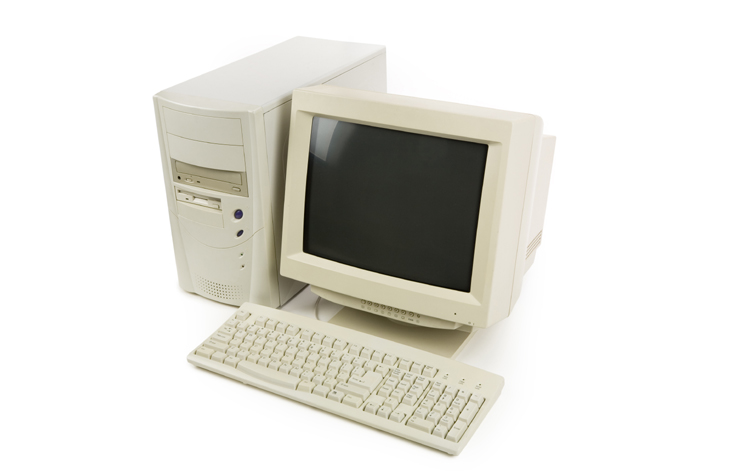
The growth of home computing in the 1980s led to smaller, cheaper, consumer-level disk drives. The first of these was only 5 MB in size. By the end of the decade, however, capacities of 100 MB were common.


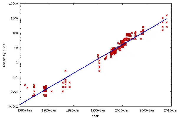
Data storage continued to make exponential progress into the 1990s and beyond. Floppy disks were replaced by CD-ROMs, which in turn were replaced by DVD-ROMs, which in turn began to be superseded by the Blu-Ray format. Home PCs with 100 GB hard drives were common by 2005 and 1 terabyte (TB) hard drives were common by 2010.

hard drive capacities 1980s 1990s exponential data storage computers


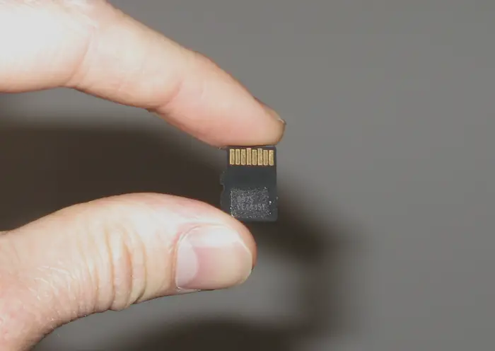
Secure digital (SD) cards arrived in the early 2000s. These provided storage in a thumbnail-sized form factor, enabling them to be used with digital cameras, phones, MP3 players and other handheld devices.
Micro-SD cards (pictured below) have shrunk this format to an even smaller size. As of 2010, it is possible to store 32 GB of data on a device measuring 11 x 15 mm, weighing 0.5 grams and costing under $100.
To put this in context: this is over 3 million times lighter and over 10,000 times cheaper than an equivalent device of 30 years ago.

microsd micro-sd micro sd card 128gb 256gb exponential trend 2010 2015 2020 future


So, what does the future hold?
It is safe to assume that the exponential trends in capacity and price performance will continue. These trends have been consistent for over half a century. Even if the limits of miniaturisation are reached with current technology, formats will become available that lead to new paradigms and even higher densities. Carbon nanotubes, for example, would enable components to be arranged atom-by-atom.
The memory capacity of the human brain has been estimated at between one and ten terabytes, with a most likely value of 3 terabytes.* Consumer hard drives are already available at this size.*
128 GB micro-SD cards are being planned for 2011* and there is even a 2 TB specification in the pipeline.*
Well before the end of this decade, it is likely that micro-SD cards (such as that pictured above) will exceed the storage capacity of the human brain.
By 2030, a micro-SD card (or equivalent device) will have the storage capacity of 20,000 human brains.
By 2043, a micro-SD card (or equivalent device) will have a storage capacity of more than 500 billion gigabytes - equal to the entire contents of the Internet in 2009.*
By 2050 - if trends continue - a device the size of a micro-SD card will have storage equivalent to three times the brain capacity of the entire human race.


Internet users 
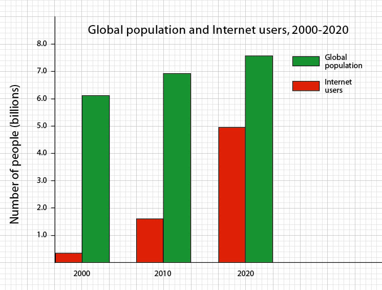
By 2020, the number of Internet users will reach almost 5 billion – equal to the entire world's population in 1987. This compares with 1.7 billion users in 2010 and only 360 million in 2000.*
Vast numbers of people in developing countries will gain access to the web, thanks to a combination of plummeting costs and exponential improvements in technology. This will include laptops that can be bought for only a few tens of dollars, together with explosive growth in the use of mobile broadband. Even some of the most remote populations on Earth will gain access to the Internet.*

2020 internet users graph growth


Moore's Law 
Moore's law describes a long-term trend in the history of computing hardware. The number of transistors that can be placed inexpensively on an integrated circuit doubles approximately every two years. This trend has continued in a smooth and predictable curve for over half a century and is expected to continue beyond 2020.
The capabilities of many electronic devices are strongly linked to Moore's law: processing speed, memory capacity, sensors and even the pixels in digital cameras. All of these are improving at exponential rates as well. This is dramatically enhancing the impact of digital electronics in nearly every segment of the world economy.
In 2011, Intel unveiled a new microprocessor based on 22 nanometre process technology.* Codenamed Ivy Bridge, this is the first high-volume chip to use 3-D transistors, and packs almost 3 billion of them onto a single circuit. These new "Tri-Gate" transistors are a fundamental departure from the two-dimensional "planar" transistor structure that has been used before. They operate at much lower voltage and lower leakage, providing an unprecedented combination of improved performance and energy efficiency. Dramatic innovations across a range of electronics from computers to mobile phones, household appliances and medical devices will now be possible.


Even smaller and denser chips based on a 14nm process are being planned for 2013, and the company's long-term roadmap includes sizes down to 4nm in the early 2020s - close to the size of individual atoms. This will present major design and engineering challenges, since transistors at these dimensions will be substantially affected by quantum tunnelling (a phenomenon where a particle tunnels through a barrier).

transistor size timeline intel computer chips future trend roadmap 2012 2013 2014 2015 2016 2017 2018 2019 2020 moores law 22nm 16nm 14nm 11nm 10nm

From the 2020s onwards, it is possible that carbon nanotubes or a similar technology will reach the mass market, creating a new paradigm that allows Moore's Law to continue.* Chips constructed on an atom-by-atom basis would reach incredible densities.
Further into the future, chips may become integrated directly with the brain, combining AI/human intelligence and dramatically enhancing our cognitive and learning abilities. This could allow technologies once considered the stuff of science fiction to become a reality - such as full immersion VR, electronic telepathy and mind uploading.
Ultimately, Moore's Law could lead to a "technological singularity" – a point in time when machine intelligence is evolving so rapidly that humans are left far, far behind.*


Supercomputers
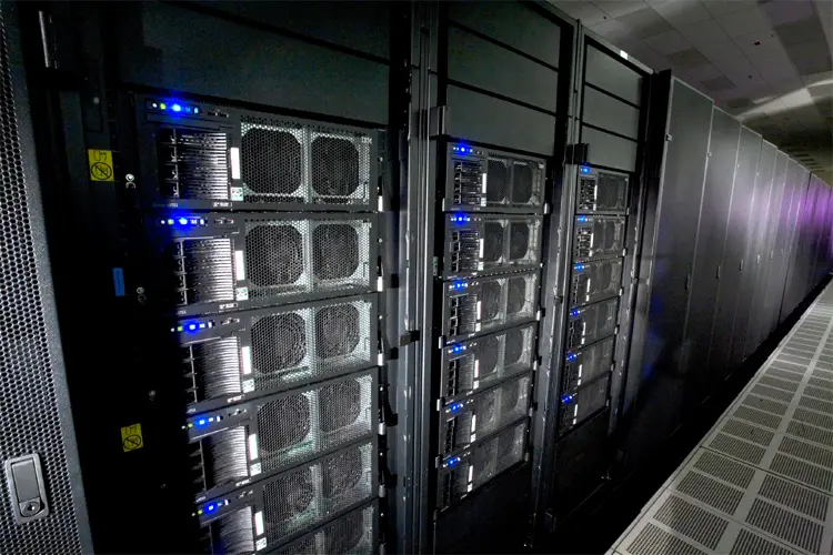
Supercomputers are very large groups of computers that work together, combining their abilities to perform tasks that individual desktop computers would be incapable of. These include highly intensive calculations such as problems involving quantum mechanics, weather forecasting, climate research, astronomy, molecular modeling and physical simulations (such as simulation of aeroplanes in wind tunnels, simulation of nuclear weapons detonations and research into nuclear fusion).
Supercomputers were first developed in the 1960s. They were designed primarily by Seymour Cray at Control Data Corporation, which led the market into the 1970s, until Cray left to form his own company, Cray Research. He then took over the supercomputer market with his new designs, holding the top spot in supercomputing for five years (1985–1990). In the 1980s, a number of smaller competitors entered the market, in parallel to the creation of the "mini-computer" market, but many disappeared in the mid-1990s supercomputer market crash.
Today, supercomputers are typically one-of-a-kind custom designs - produced by traditional companies such as Cray, IBM and Hewlett-Packard - who had purchased many of the 1980s companies to gain their experience.

supercomputer future trends 2010 2012 2020 2025 timeline graph chart diagram roadrunner IBM
Roadrunner, a supercomputer built by IBM. In 2008, it became the first 1.0 petaFLOP system. Credit: Los Alamos National Laboratory

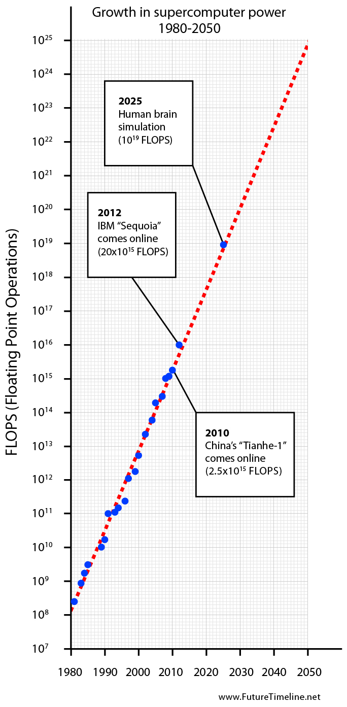
Since October 2010, China has been home to the world's fastest supercomputer. The Tianhe-1A supercomputer, located at the National Supercomputing Center in Tianjin, is capable of 2.5 petaFLOPS; that is, over 2½ quadrillion (two and a half thousand million million) floating point operations per second.*
America will take the lead once again in 2012, when IBM's Sequoia supercomputer comes online. This will have a maximum performance of 20 petaFLOPS; nearly an order of magnitude faster than Tianhe-1A.* IBM believes it can achieve exaflop-scale computing by 2019; a thousandfold improvement over machines of 2010.*
For decades, the growth of supercomputer power has followed a remarkably smooth and predictable trend, as seen in the graph below. If this exponential trend continues, it is likely that complete simulations of the human brain and all of its neurons will be possible by 2025.* In the early 2030s, supercomputers could reach the zettaflop scale, meaning that weather forecasts will achieve 99% accuracy over a two week period. By the 2050s, supercomputers may be capable of simulating millions - even billions - of human brains simultaneously. In parallel with developments in artificial intelligence and brain-computer interfaces, this could enable the creation of virtual worlds similar in style to the sci-fi movie, The Matrix. It is even possible that we are living in such a simulation at this very moment, without realising it.*

supercomputer future trends 2010 2012 2020 2025 timeline graph chart diagram roadrunner IBM sequoia tianhe-1

Saturday 28 March 2015

Welcome to my site spotturns

reddyprasad reddivari
spotturns logo by reddyprasad

                               Welcome to my site spotturns

the meaning of spotturns i wana tell you first,spotturns consisting of two words spot+turns,i mean if you follow my site means you can change your thoughts as fast as light (3*10^8 m/s)  and your life can turn at spot

Because human life is 30% how you make it &&remaining 70% how u take it.
That means you have to face the problems and solve it your brain not your strengths

And our success depends on quality of our thoughts, but the quality in our thoughts comes from on good knowledge hubs

i think my site can show you the way to updates your knowledge towards science and technology


Link address:


                                 Thank you for visiting my site


electrical projects for you

this is the site to make your thoughts into the actions just go through to wash your brain towards technology

https://sites.google.com/site/electricalprojects4u/

electical project ideas
electrical projects 4 u by reddyprasad reddivari

Tuesday 24 March 2015

Clap Switch Circuit Electronic Project Using 555 Timer & BC-547 Transistors

Clap Switch Circuit Electronic Project Using 555 Timer & BC-547 TransistorsClap Switch Circuit Electronic Project Using 555 Timer

Clap Switch Circuit Electronic Project Using 555 Timer & BC 547 Transistors

Introduction

Clap Switch is a basic Electronics mini-project, made with the help of the basic components. Clap Switch has the ability to turn ON/OFF any electrical component or circuit by the clap sound.
It is known as Clap Switch, because the condenser mic which will be used in this Project will have an ability to take the sound having same pitch as the Clap sound as the input. Although it doesn’t mean that the sound will have to be of Clap sound, it can be any sound having the same high pitch as of Clap. We can also say that it converts the Sound energy into the Electrical Energy, because we are giving an input to the circuit as a sound whereas the Circuit gives us the output as a LED glow (Electrical Energy).
Also Read:

Required Components

As already mentioned, this project is basic Electronics mini-project, so this project is made of the basic components. Following is the list of the components required to make the Clap Switch.
  1. 1K, 4.7K, 47K, 330 and 470 ohm resistors
  2. 10µF and 2 100nF capacitors
  3. Electric Condenser mic
  4. Two BC547 transistors
  5. LED
  6. 555 timer
  7. 9V Battery

Working Principle of Clap Switch Circuit

This circuit (As shown below) is made with the help of Sound activated sensor, which senses the sound of Clap as input and processes it to the circuit in order to give the Output. When sound is given as the input to the Electric Condenser Mic, it is changed into the Electrical Energy as the LED turns on. LED turns ON, as we give sound input and it turns OFF automatically after few seconds. Turn-On LED timer can be changed by varying the value of 100mF capacitor as it is connected with 555 timer whose main purpose is to generate the pulse.
Although the name of the circuit is the Clap Switch, but you are not restricted to give input as the Clap only. It can be any sound, having same pitch as of Clap so this can also be called as “Sound Operated Switch”. This circuit is mainly based on transistors, because the negative terminal of Mic is directly connected with the transistor. In this circuit, we haven’t used any Electronic Switch to turn on/off the circuit, so when you are connecting the battery with the circuit, it means your circuit is now turned ON and it will take the inputs in the form of Sound Energy. You can modify this circuit by using Relay as Electronic Switch to turn the circuit ON or OFF.
As soon as we give the sound input to the circuit, it amplifies the sound signals and proceeds them to the 555 timers which generates the pulse to the LED, making it turn ON. You are to make sure, that the negative side of the Condenser mic is connected with the amplifier or the circuit will heat-up and may not working with different models of transistors etc. You cannot increase the sensitivity of the Condenser mic for long usage, it has short range by default. It is also applicable for the LAMP, so this circuit has many opportunities for modification.
Clap Switch Circuit Diagram electronic projectClap Switch Circuit Diagram

Advantages & Disadvantages

  1. It can used to turn ON and OFF the LED or LAMP simply, by clapping your hands.
  2. We can also remove LEDs and place a FAN or any other electric component on the output in order to get desired result.
  3. The Condenser Mic used in this circuit has the short range as a default, which cannot be varied.

Applications

Clap Switch is not restricted to turn the LEDs ON and OFF, but it can be used in any electric appliances such as Tube Light, Fan, Radio or any other basic circuit which you want to turn ON by a Sound.

Why Parallel Connection is Mostly Preferred over Series Connection?Why Parallel Connection is Mostly Preferred over Series Connection?

Introduction to Series & Parallel Connections

The use, application and importance of series and parallel circuit connection today cannot be over emphasized. The application of series and parallel circuit connection can be evidently seen in our homes, school halls and in our street lights. With the press of a button, all the Bobs in our sitting rooms are turned on. some refer that the bobs in their homes should have different switches.
Well, it’s not a magic when more than three electric bobs or loads are controlled by one switch. A load is anything i.e. it could be an appliances, electric bobs or even ceiling fans that consumes electrical energy when connected to a power supply. The electric bobs, televisions, refrigerators etc can all be referred to as a load. The bobs convert electrical energy into light and heat form of energy. Fans convert the electrical energy into mechanical energy.
Introduction to Series & Parallel Connections
The type of connection done to our ceiling fans, electric bobs will determine if they will have a common switch or not. Series circuit connection gives us the opportunity to connect more than two loads to a common switch. Street lights are a very good example of this. Parallel circuit connection makes it possible for us to connect loads to their individual switch. Both series and parallel circuit connection are good but one is mostly preferred over the other for one reason or the other. Before we talk about the reason why parallel circuit connection is preferred over series connection, let’s recall what series and parallel connections are first.

SERIES CIRCUIT

A series circuit is a circuit in which resistors or loads are connected end to end so that the circuit will have only one path through which electric current flows. Thus, when a number of resistors are connected in series, the effective resistance (total resistance in the circuit) is gotten by adding the individual resistance algebraically. That is to say, if we have resistors with resistance R1, R2, R3 …Rn connected in series, then;
Reff = RT = R1 + R2 + R3 + …Rn.
In series connections, the same current flows across all the branches of the circuits, but different voltage across it thus making the resistors to have different voltage across them. Each resistor or load will experience a voltage drop. The applied voltage is equal to the sum of the voltage drop across the different parts of the circuit. Voltage drop is proportional to the resistance current being the same throughout the circuit. When loads are connected in series, the loads will tend to have a common switch. This kind of connection is employed in school halls, street lights.

Uses & Application of Series Connection

Some people connect security lights in their homes in series which will make them to have common switch. The problem with this kind of connection is that when a load develops a problem, the other connected system will fail. It’s an all or none type of circuit connection. Till a load gets energy before it delivers it to the other and the one to deliver fails, there will be a black out.
Series circuit connections are common and greatly employed in electrical equipments. The tube filaments in small radios are usually in series. Current controlling devices are always connected in series with the device that they protect. Fuses are connected in series with the device they protect, Automatic house-heating equipment has a thermostat, electromagnetic coils, and safety cut-outs connected in series with a voltage source etc.

PARALLEL CIRCUIT

Resistors, loads are said to be connected in parallel when the end of each of the resistors or loads have a common point or junction and the other ends are also connected to a common point or junction. Such circuits are known as parallel circuits.
Unlike the series circuit connection, when finding the total (effective) resistance in a parallel circuit, the reciprocal of the individual resistance is taken. Thus, when a number of resistances are connected in parallel, the reciprocal of the effective resistance is given by the arithmetic or algebraic sum of the reciprocal of the individual resistance.
1/Reff or 1/RT = 1/R1 + 1/R2 + 1/R3 …1/Rn.
Parallel circuit connection have the same voltage flowing across all the branches of the circuits. Different resistors have their individual currents.

Uses & Application of Parallel Connection

Parallel circuit connection is very common in use. Various lamps and electrical appliances in our homes are connected in parallel so that each of the lamps or bobs and appliances can be operated independently. For us to have control over the individual lamps or loads, they have to be wired in parallel.

ADVANTAGE OF PARALLEL CIRCUIT CONNECTION OVER SERIES CIRCUIT CONNECTION.

A series circuit connection is an all or none type of circuit connection. Meaning that if one of the appliances fails, all the other appliances will also fail which is why this type of connection is good only when we want to protect a device.Advantage of parallel circuit connection over series circuit connectionWhen a fuse gets burnt for instance due to high current, then the appliance it protects will not be damaged because current will no longer reach it. While series connection is an all or none, parallel circuit connection gives you the opportunity to give the loads and the appliances their individual switch. Parallel connection offers resistance to the flow of current compared to series connection.
A 100 ohms and a 150 ohms resistors connected in parallel will have less effect on electric current compared to 50 ohms and 40 ohms resistors connected in series. In electronic devices, parallel connection is paramount. The cells in a power bank are all connected in parallel. Parallel connection makes electrical energy to last longer. The cells themselves have their internal resistance, so if they were connected in series, some of the energy will be lost overcoming the internal resistance since it’s effect is high when in series than when in parallel.

Automatic Street Light Control System.(Sensor using LDR & Transistor BC 547.) Very Simple.

Automatic Street Light Control System.(Sensor using LDR & Transistor BC 547.) Very Simple.


Briefing:

Her is our new simple Electrical/Electronics project about Automatic Street Light Control System. 
  • it is a simple and powerful concept, which uses transistor (BC 547 NPN) as a switch to switch ON and OFF the street light system automatically.
  • It automatically switches ON lights when the sunlight goes below the visible region of our eyes. (e.g in evening after Sunset). 
  • it automatically switches OFF lights when Sunlight fall on it  ( i.e on LDR ) e.g in morning, by using a sensor called LDR (Light Dependent Resistor) which senses the light just like our eyes. 
Advantages:
  • By using this Automatic system for street light controlling, we can reduce energy consumption because the manually operated street lights are not switched off properly even the sunlight comes and also not switched on earlier before sunset. 
  • In sunny and rainy days, ON  and OFF time differ noticeably which is one of the major disadvantage of using timer circuits or manual operation for switching the street light system.
Enough….Now lets begin ( Step by Step)

Requirements
  • LDR Light Dependent Resistor
  • Take 2 transistors. (NPN transistor- BC547 or BC147 or BC548)
  • Resistor- 1K, 330Ohm, 470 ohm
  • Light emitting diode (LED) – Any color
  • Connecting wires- Use single-core plastic-coated wire of 0.6mm diameter (the standard size)-You can use wire that is used for Computer Networking.
  • Power supply-6V or 9V
Procedure
  • Insert first transistor Q1-BC547 (NPN) on breadboard (or general PCB) as shown in the circuit diagram 1.
  • Connect another transistor Q2- BC547 (NPN) on breadboard as in step 1.
  • Connect  wires across emitter pin of both transistors and –ve terminal of battery (lowest/ bottom row of breadboard.)
  • Connect  a wire across Collector pin of transistor Q1 and Base pin of transistor Q2.
  • Connect a resistor 1K across positive terminal of battery (topmost row of breadboard) and Collector pin of transistor Q1.
  • Connect  Light Dependent Resistor (LDR) across positive terminal of battery (topmost row of breadboard) and base terminal of transistor Q1.
  • insert a resistor- 330 Ohm across base pin of transistor Q1 and negative terminal of battery (lowest bottom row of breadboard).
  • Connect a resistor 330R across positive terminal of battery (topmost row of breadboard) and anode terminal of LED (Light emitting diode) & Connect the cathode terminal of LED to Collector pin of transistor Q2.

The simple circuit is ready for testing now. Connect 6V battery terminals to the circuit as show in fig and see the output. As you block light falling on Light dependent resistor(LDR), the LED glows.
LED GLOWS EVEN IN LESS DARKNESS. Use torch light or Lighter if the LED glows in less darkness. in addition, you can try to adjust the sensitivity of this circuit by using a variable resistor in place of R1-300Ohm. Try this circuit with other resistances as well, (e.g, 1KΩ, 10KΩ and 100KΩ, etc)

PICs Story: ( For Zooming View images in new tab)

 Requirements:


Circuit Diagram 1.Automatic Street Light Control System.(Sensor using LDR & Transistor BC 547.) Very Simple.  We have tried this one in this tutorial bu you can also try the second one

Circuit Diagram 2 .Automatic Street Light Control System.(Sensor using LDR & Transistor BC 547.) Very Simple.
As Light is falling on LDR ( Light Dependent resistor) So LEdoes not glow. ( LED = Off)                                                            Image Taken Our from Video

You can see now that we have blocked light falling on Light dependent resistor(LDR), so the LED glows ( LED = ON)             Image Taken Out from Video